Cart Total Items (0)

Cart

Product Reference
Download
  • Our Brochures Download
  • Our Brochures Download

Screw feeder Assembly Improvement

PROJECT DETAILS
MANUFACTURERREXLINE ENGINEERING
MANUFACTURER’S DESCRIPTION/PART NUMBERScrew Feeder Assembly
MATERIAL NUMBERN/A
CLIENT 
PURCHASE ORDER279539
DATE OF PURCHASE09/03/2019

Material Information

a) Rubber: REXLINE PREMIUM 38

REXLINE Premium is a natural enriched, premium compound uniquely engineered for wet applications. REXLINE Premium offers excellent abrasion resistance, elongation and strength required to handle fine ores in the hardest condition. The precise mastication of the compound provides outstanding properties and performance to Premium rubber.

Size (m)10 × 1.5
Thickness (mm)6 mm
ColourDistinctive Pink
ProcessesWear Protective Lining
Surface FinishSmooth Top – Buff Back
Technical Information
Test Method Value
Polymer Not Recommended
Hardness ASTM D2240 38 ± 5 Shore A
Specific Gravity ASTM D297 0.98 ± 0.05
Abrasion Loss ASTM D5963 80 mm³
Tensile Strength ASTM D412 25 Mpa
Elongation ASTM D412 900%
Tear Resistance ASTM D624 44 Kg/cm
Resilience 75%
Compression Set ASTM D395 (Method B) 20%
Ozone Fair
Temperature Range -40˚ to +70˚ C

b) Ceramic: Ceramic Rubber Mats

Ceramic rubber mats are supplied with different tile shapes and sizes made perfectly suited to your requirements. Ceramic tiles are ideally suited for lining against high wear areas such as cyclone launders, mill feeders etc.
Ceramic Mats are available with CN layer at the back to enable ease of application.

General Information
SurfaceOverall ThicknessCeramic on RubberTile Shape
Shaft Surface8 mm4 on 4Square Tiles
Freight Surface10 mm6 on 4Square Tiles
Technical Specifications
Description 92% Ceramics 95% Ceramics ZTA
Alumina Content 92% 95%
Density (g/cm³) 3.61 3.62 4.1
Rockwell Hardness (HRA) 85 88 90
Vickers Hardness (HV10) 1200 1350 1400
Fracture Toughness, Kic (Mpa.m½) 3.6 4.1 5.5
Compressive Strength (MPa) 2000 2281 2924
Wear Volume (cm³) 0.02 0.017 0.009
ANALYZING THE SITUATION

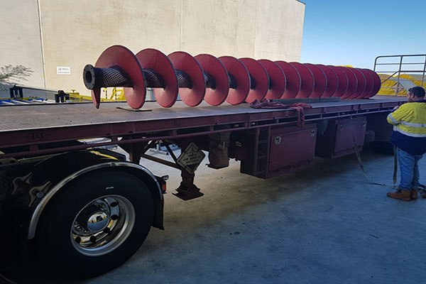
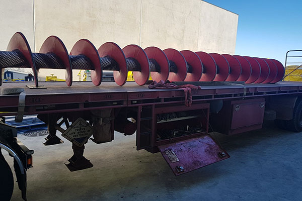
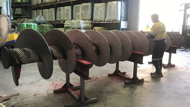
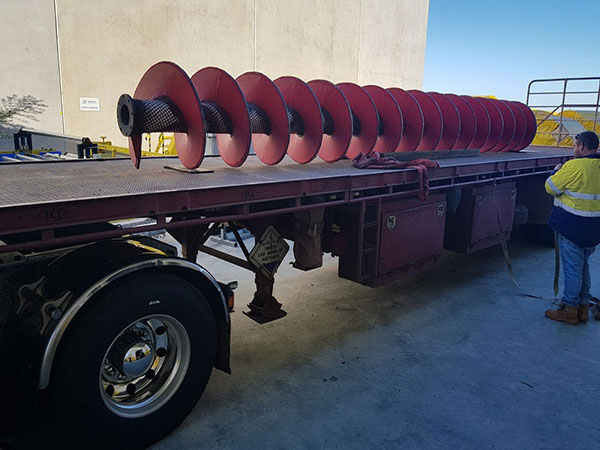
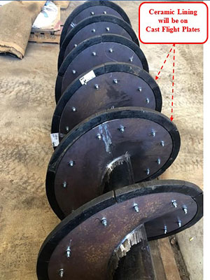
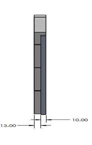
A screw conveyor is a mechanism that uses a rotating helical screw blade, called a flighting, usually within a tube, to move liquid or granular materials. They are used in many bulk handling industries. In our case, the company is using it to transport lithium fine particles for mining purposes in Mt Marion, WA.

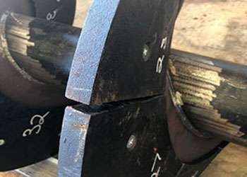
After discussing with the Site Maintenance Contracting team, the previous rubber lining that was applied on the screw feeder didn’t last long and worn out very quick.

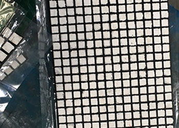
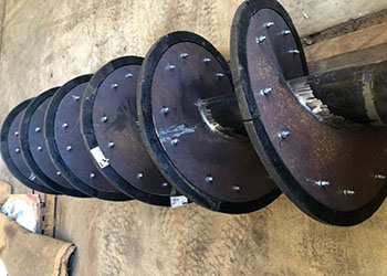
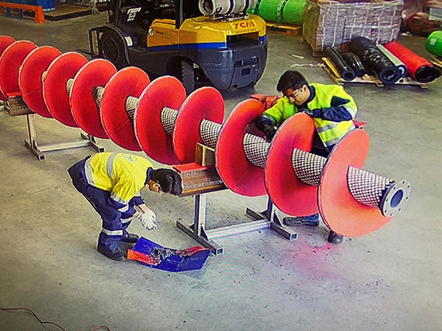
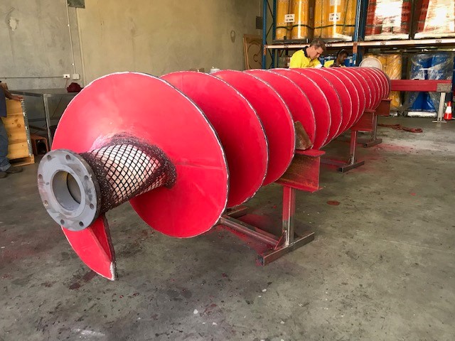
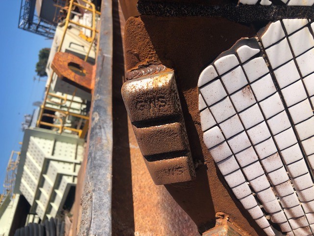
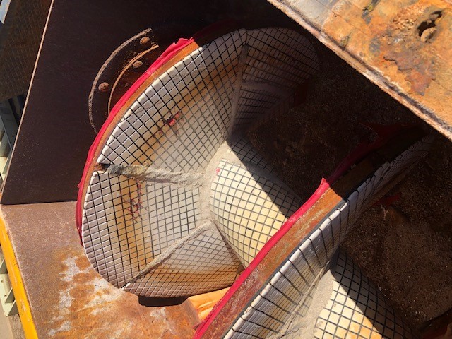
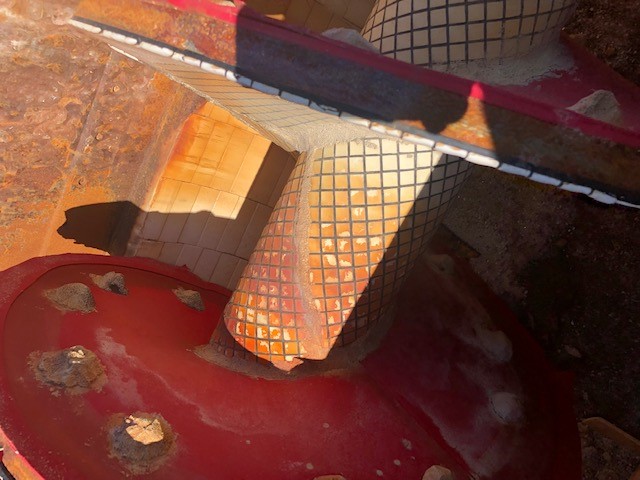
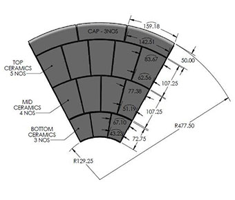
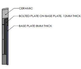
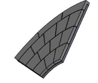
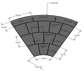
After doing some test and analyzing the situation, we decided to apply a special Rexline Engineering ceramic liner on the flight surfaceto withstand a higher amount of abrasion.

PROJECT BENEFITS REVIEW
PARAMETERBENEFITS
SERVICE LIFECurrent service Life of REXLINE Premium Rubber & Ceramic Mats: 39 weeks
COSTReplacement and Maintenance costs of the screw feeder was reduced by a minimum of 40% considering for a year’s worth of service life.
RUBBER & CERAMIC LINING WORKS

Since the shaft needs to be lined with ceramic, our engineering team has cut the ceramic mats to the required size to suit the shaft of the screw feeder. During this process its important to apply enough amount of adhesives so we have enough bonding strength to hold the tiles and flight steel together.

Quality control before delivering the screw feeder to client. This step is important to make sure the final product respects the dimensional and geometrical tolerances given by the client.

The screw feeder assembly delivered to client in good condition. Project managed to be completed ahead of schedule thanks to all REXLINE team that organize and work together as a team.

Screw Feeder After Service Photos

Proposal For Screw Feeder Assembly With Cast Liner Plates

STAGE 2

INTRODUCTION

This document details the New Proposal for the Screw Feeder Assembly by using Cast Ceramic blocks lined on Cast Ceramic plates and in gap between ceramic plate and mother plate.

CURRENT SCREW FEEDER DESIGN AND TECHNICAL ISSUES

  • Current design of screw feeder assembly includes Bolting of Cast Flight Plates onto Welded Adaptor Plate of the assembly. This posed a lot of challenges during Assembly and lining application stages of the project. Some of them are:
  • Misalignment between Flight Plates leading to Protruded Sections on the This causes localized high wear of the plates.
  • Clearance and Gaps more than 10 – 12mm between Flight plates leading to excessive labor to repair and fill up these gaps with Ceramic Epoxy.
  • Flights are not the correct size in length. They should extend all the way to down to the top of the shaft.
  • Due to manufacturing defects, The Cast Flight plates are brittle and are filled with porosity. This posed challenge of the plates cracking even in light impacts during assembly and application stages.
  • Exposed Bolts and Nuts of the bolted-on Flight plates during application can lead to wearing out during operation and Flight plates falling of the flights.
  • Bolts are not of the correct grade. The bolts were torqued to the correct torque setting but were still sheering off under when tightening.
  • The Whole assembled Screw feeder needs to be supported on a transport frame to allow free spinning and access when installing the lining. Also, this will prevent damage during transport and help with curing and drying times to be sufficient without pressure on the installed linings.
Figure 1: Screw Feeder Assembly: Flights Plates made out of Cast Bolted on the Adaptor Plate
Figure 2: Gap in between Plates
Figure 3: Misalignment in the Plates
PROPOSED NEW DESIGN OF SCREW FEEDER ASSEMBLY
  1. Pre-Cast Ceramic Tiles will be bonded on Pre-cast ceramic plate bolted on the Mother plate and in the gap between cast plate and mother plate. As shown in figure 5, the Cap, Top Ceramic and Mid Ceramic segments will be bonded on Pre-cast Ceramic plates, Whereas Bottom Ceramic segment will be directly bonded on to the mother plate. The width of the bottom ceramic will be increased to size to align the profile. The tiles will be pre-cast in segments to suit the shape and profile of the flight.
  2. The Pre- Cast Ceramic tiles will set in four rows on the flight as shown in figure. The top edge will be covered by L – shaped cap Liner to protect the edge of flight.
  3. The finished diameter after the cast ceramic cap is installed will match the previous diameter of the cast plates.

Figure 5: Proposed Cast Ceramic Block with Dimensions

Figure 6: Side View of the Ceramic on the Plate

Figure 7: Isometric View

Proposal For Screw Feeder Assembly Without Cast Liner Plates

STAGE 3

INTRODUCTION

This document details the New Proposal for the Screw Feeder Assembly by using Cast Ceramic blocks directly onto the main plate instead of bolting cast flight plates.

CURRENT SCREW FEEDER DESIGN AND TECHNICAL ISSUES

Current design of screw feeder assembly includes Bolting of Cast Flight Plates onto Welded Adaptor Plate of the assembly. This posed a lot of challenges during Assembly and lining application stages of the project. Some of them are:

  • Misalignment between Flight Plates leading to Protruded Sections on the This causes localized high wear of the plates.
  • Clearance and Gaps more than 10 – 12mm between Flight plates leading to excessive labor to repair and fill up these gaps with Ceramic Epoxy.
  • Flights are not the correct size in length. They should extend all the way to down to the top of the shaft.
  • Due to manufacturing defects, The Cast Flight plates are brittle and are filled with porosity. This posed challenge of the plates cracking even in light impacts during assembly and application stages.
  • Exposed Bolts and Nuts of the bolted-on Flight plates during application can lead to wearing out during operation and Flight plates falling of the flights.
  • Bolts are not of the correct grade. The bolts were torqued to the correct torque setting but were still sheering off under when tightening.
  • The Whole assembled Screw feeder needs to be supported on a transport frame to allow free spinning and access when installing the lining. Also, this will prevent damage during transport and help with curing and drying times to be sufficient without pressure on the installed linings.
Figure 1: Screw Feeder Assembly: Flights Plates made out of Cast Bolted on the Adaptor Plate
Figure 2: Gap in between Plates
Figure 3: Misalignment in the Plates

PROPOSED NEW DESIGN OF SCREW FEEDER ASSEMBLY

  1. Pre-Cast Ceramic Tiles will be bonded on Pre-cast ceramic plate bolted on the Mother plate and in the gap between cast plate and mother plate. As shown in figure 5, the Cap, Top Ceramic and Mid Ceramic segments will be bonded on Pre-cast Ceramic plates, Whereas Bottom Ceramic segment will be directly bonded on to the mother plate. The width of the bottom ceramic will be increased to size to align the profile. The tiles will be pre-cast in segments to suit the shape and profile of the flight.
  2. The Pre- Cast Ceramic tiles will set in four rows on the flight as shown in figure. The top edge will be covered by L – shaped cap Liner to protect the edge of flight.
  3. The finished diameter after the cast ceramic cap is installed will match the previous diameter of the cast plates.
Figure 5: Proposed Cast Ceramic Block with Dimensions
Figure 6: Side View of the Ceramic on the Plate
Figure 7: Isometric View