Condition Monitoring System
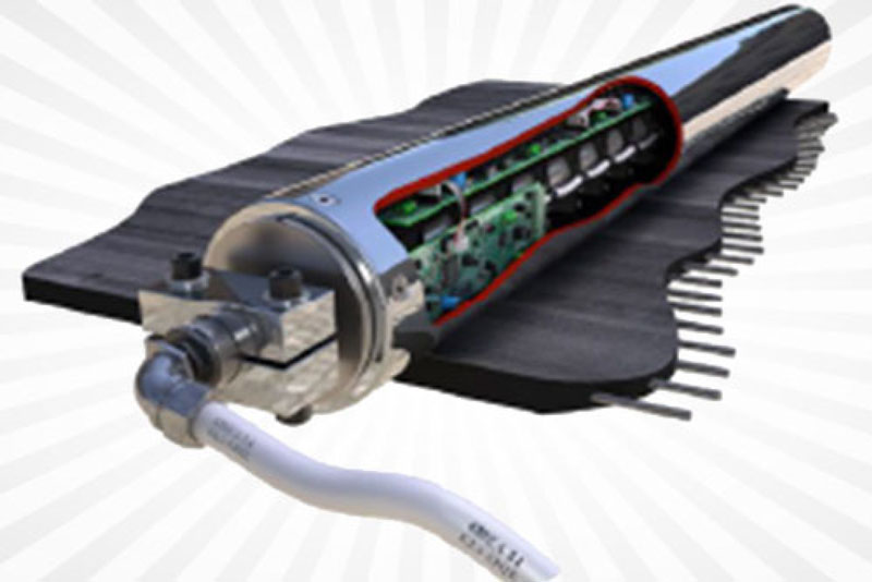
Rexline’s Condition Monitoring System represents the very latest state-of-the-art in steel cord belt condition monitoring. The Condition Monitoring System uses a patented high-resolution Roller Transducer to detect belt carcass and splice damage. When employing highresolution Transducers to detect such damage, it is essential that the Transducer be as close to the cords as possible and that the belting be dynamically stable, vertically.
Damage Detected and Quantified Includes:
- Broken cords
- Rusted or corroded cords
- Kinked cords (vertical plane)
- Fatigued cords (if cords have discontinuity in filaments consistent with plastic deformation and ductile failure)
- Missing cords
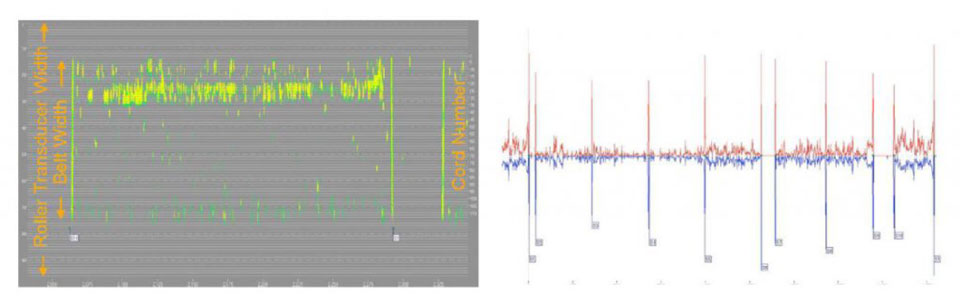
- Splice anomalies, using magnetic signature comparison
Accurate location and quantification of damage is achieved without the need to stop the conveyor for visual inspection. The belt carcass is magnetized during scanning, leaving a magnetic ‘fingerprint’ in the belting, which aids in exact location of Events of Interest, if belt maintenance is needed. There is no limit to belt width, length, speed or product conveyed.
As well as data on demand, the Belt Scanner offers a 24/7 Disastrous Event Detection (DED) feature, where the belt condition is continuously monitored against a user-defined level of damage. If this level is exceeded, the conveyor can be stopped. A Programmed Parking option allows belt maintenance personnel to park the belting automatically where they want, for belt repairs etc., in a splicing station.
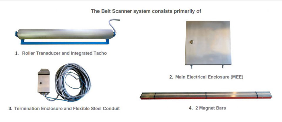
Hardware
Software
The Condition Monitoring System is a software-based device. All device configuration and operation is performed under proprietary software which runs on Windows 98 – Windows 8. Data Analysis software is available, which also runs on Windows.
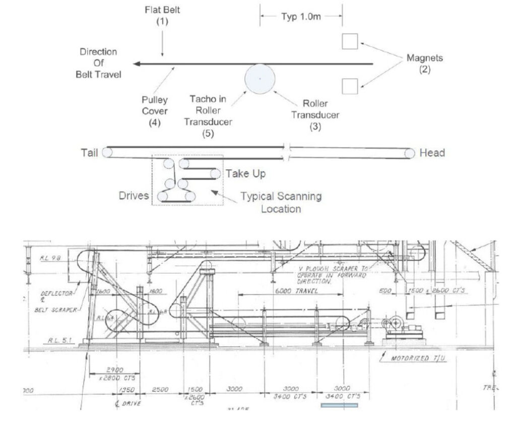
Device Location
The Condition Monitoring Roller Transducer is non-magnetic and is located in a flat section of belting, in contact with the Pulley Cover, where it is used to provide belt stabilization and to ensure minimum transducer-to-cord distance.
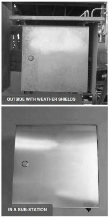
The 24/7 version of the Belt Scanner employs a Main Electrical Enclosure (MEE), which consists of a stainless steel enclosure (IP69K), containing the system power supply, electronics and communication module. The MEE communication module allows connectivity with the system, either at short range via serial or Ethernet data cables, or long range over the Internet via a Mobile Broadband service, or site LAN via VPN.
It is strongly recommended that the MEE be located inside an electrical substation or similar building, away from direct sunlight and wash down. Where this is not possible, integrated weather shields can be built onto the enclosure.
Maintenance
The Condition Monitoring equipment requires very little maintenance other than general housekeeping by ensuring the system is kept relatively free from product build-up etc.
Visual inspection should be carried out on a regular basis to confirm all mounts are secure. Light hose down is recommended on a regular basis. The Roller Transducer needs to be checked regularly to ensure it is still in intimate contact with the belting. Build up of product on the Roller Transducer will degrade the data quality.
Technical Specifications
Technical specifications vary with each system supplied, therefore the values shown below are for a typical system.
| Roller Transducer | |
| Construction | Stainless Steel |
| Dimension | 140.0 (Dia) x 1,500 (L) mm * |
| Net Weight | 60kg* |
| Operating Temp | 13 ~ 158°F(-25 ~ 70°C), 5 to 95% RH |
| Storage Temp | 40 ~ 176°F(-40 ~ 80°C), 5 to 95% RH |
| Magnet Bar (per each) | |
| Construction | Stainless Steel |
| Dimension | 40.0 (H) x 40.0 (W) x 1,500 (L) mm* |
| Net Weight | 9kg* |
| Operating Temp | 13 ~ 158°F(-25 ~ 70°C), 5 to 95% RH |
| Storage Temp | 40 ~ 176°F(-40 ~ 80°C), 5 to 95% RH |
| Main Electrical Enclosure (MEE) | |
| Construction | Stainless Steel IP69K |
| Dimension | 400 (H) x 400 (W) x 250 (D) mm |
| Net Weight | 20kg* |
| Power Supply | 110 / 240 VAC 50 / 60Hz or 24 VDC |
| Power Consumption | 10W |
| DED Output | Relay, Form C – 5A 240 VAC |
| Relay Action | N.O. |
* varies from system to system.
Rip Detection Systems
Rexline’s Rip Detection Systems represent the latest in acoustic-based longitudinal conveyor belt rip detection systems. Longitudinal rips are one of the most disruptive problems faced by operators of steel cord conveyor belting and Rexline’s acoustic-based systems have been providing reliable protection against these issues for many years.
It is unique in that it can be fitted to most steel cord conveyor belting without modifying the belting. No sensor loops or antennae are required.
Principle of Operation
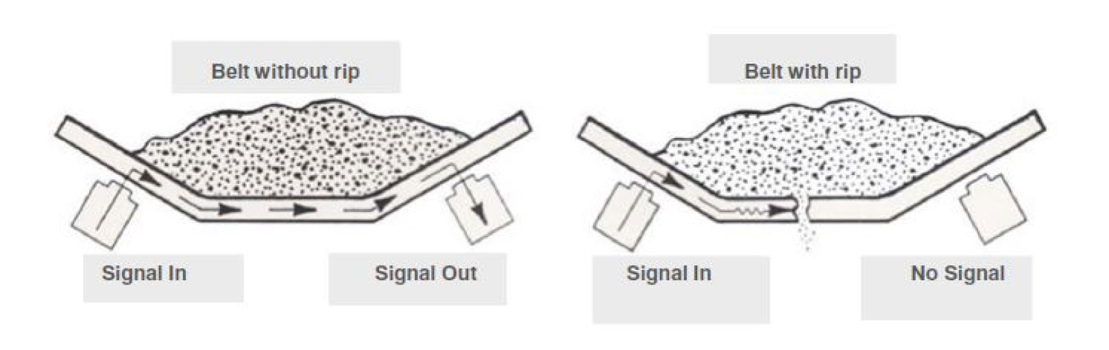
The Rip Detection System injects acoustic energy into the target belting, at the sensing location and this energy propagates across the belt using the rubber and steel matrix as the transmission medium.
The energy is injected by a transmitter transducer and sensed by a number of receiver transducers, located at various positions across the belt. When a longitudinal rip occurs between the transducers, the level of acoustic energy arriving at a receiver is either reduced or lost completely. This reduction of energy level is used to detect the rip.
Hardware
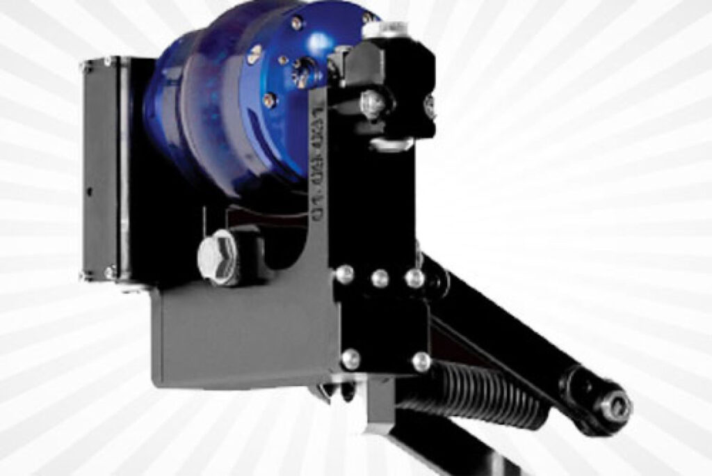
The ‘front end’ of the device consists of a number of transducers (maximum of nine), installed equidistant laterally across the belt. These transducers contact the underside of the belting and are biased against the surface using spring loaded mounts.
These mounts are fitted to a main transverse support, which is purpose-built for each conveyor structure. Once a mount’s lateral location is established it is adjusted for height. The mounts are designed to minimise product build-up and embody ‘parking’ pins so that a transducer can be locked away from the belt surface, to facilitate maintenance. The lateral separation of the transmitter and receiver transducers (transducers are interchangeable), depends on the construction of the belt.
Different types of belting provide different characteristics, as far as acoustic transmission is concerned, however, most common steel cord belting, including M and N grade, B grade, SAR and LRR compounded belts are good hosts. Typical lateral transmitter-to-receiver separation on the above compounded belts is in the range 300mm – 700mm. This separation, together with the belt width, will dictate how many transducers are required to span the active portion of the belting. The number of transducers required to span the belting will determine the cost of each system.
The transducers are replacement items as they are contact components. Transducers can be replaced easily via one M12 mounting bolt and two plugs and sockets and a re-build service is available to minimise cost of transducer replacement. Typical transducer life is in the range nine months – five years.
Each transducer incorporates sophisticated onboard electronics which monitor and log all ‘vital’ life signs and relay this information back to the Main Electrical Enclosure (MEE).
Transmitter and receiver electronic modules are sited close to the sensing location and a single multi-function cable is run to the MEE. These modules are housed in IP 68 rated 316 stainless steel enclosures and a tacho generator is also fitted to a local idler roller.
The MEE is a stainless steel IP 69K rated enclosure and contains the power supply, motherboard, memory and communication modules. A dedicated single phase electric mains supply of 110VAC / 15amp or 240VAC 10amp is required for the MEE.
Software
The Rip Detection System is software controlled. All machine parameters are adjusted and monitored in software. Important machine operational parameters are given ‘windows’ during commissioning. Any violation of a window is logged, established as an “Alarm”, and passed on to appropriate personnel via e-mail or SMS, as provided for during set-up. There are various levels of Alarms, so the nature of an Alarm can be assessed and sent only to the appropriate destination, minimising inconvenience. All receiver data and events of interest are logged and may be downloaded for analysis.
Software updates can be downloaded ‘live’, no technician site visit is necessary. To achieve this, the device MUST be connected to the Internet. This can be done via Third Generation (or later) mobile phone networks or a site LAN/WAN using an Ethernet connection.
Device Location
The transducers and mounts are normally located just downstream from the last load point. This site is chosen as the primary location because experience suggests that most longitudinal rips occur at a load point. It should be noted that this is not always the case, so consideration should be given to multiple locations, including horizontal curves and inside transfer buildings. The MEE is usually located in an electrical sub-station or similar, away from direct sunlight and severe hose down.
Maintenance
- Maintenance is usually limited to transducer replacement and this has been covered under HARDWARE. With this in mind, transducer change-out has been designed to be as simple as possible. No unusual tools are required and no special skill set needed.
- The mounts are extremely reliable and durable, but again, can be easily replaced if necessary.
- All enclosures are IP 68 rated, or better, and are fabricated from 316 stainless steel.
- All electronics have been designed and built with their intended use in mind.
- Short circuit and over voltage protection is standard.
Troubleshooting
- The device is a mature product. It has been rigorously tested over many years and is very robust and reliable.
- A video surveillance camera is usually fitted at the sensing location as part of the installation so that events, such as false trips, can be observed and/or recorded and then correlated with machine data to facilitate troubleshooting.
- Occasionally mobile phone networks suffer outages. This will not effect the operation of the machine, if this is the primary method of Internet connectivity, but will prevent alarms and diagnostic data from being sent and downloaded for analysis.
- Because the device does not need a full-through rip to operate, aggressive setting of the Trip Threshold can see the device trip on partial depth rips.
Rexline’s Cover Care
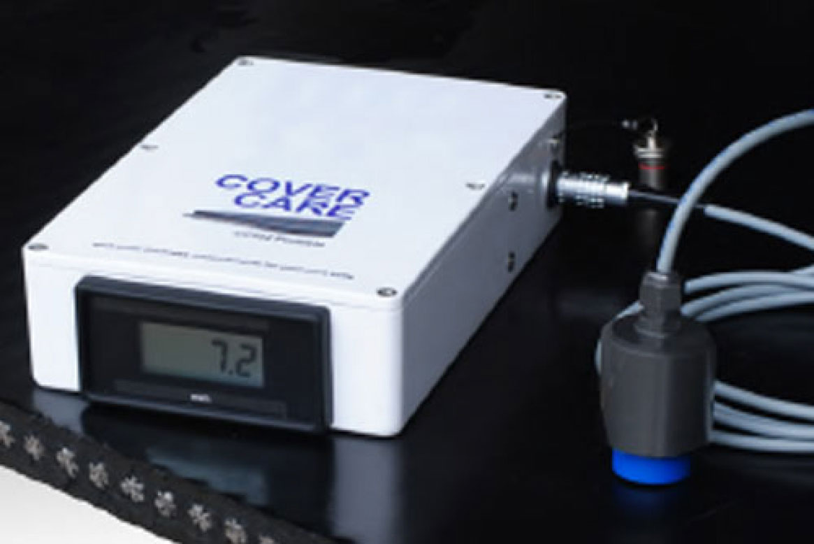
Rexline’s Cover Care is a device specifically created to facilitate spot measurement of the cover thickness in steel cord conveyor belting. It was created out of frustration created through the common use of ultrasonic-based devices to make this type of measurement. While ultrasonic devices are appropriate for use over a wide range of non-destructive testing, the measurement of cover thickness in steel cord conveyor belting is problematic.
The Cover Care is an inductive-based device, which makes this type of measurement very simple and very accurate.
It is a fully portable instrument which is powered by a re-chargeable internal 12Volt-1.3Ah battery and has an endurance of approximately nine (9) hours on a full charge. It uses an inductive hand-held probe to detect the steel cords. The output from the probe is delivered to a microprocessor which calculates the distance of the probe face to the top of the cords, using a unique algorithm or ‘Cover Care Belt Profile’ and displays the value in mm on an easy-to-read display.
Unlike ultrasonic instruments used for the same purpose, no coupling medium is necessary and the measurement accuracy is not affected by changes in ambient temperature.
Measurement is in the range 0.0mm – 50.0mm and resolution is +/- 0.1 mm.
Calibration of the instrument is simple and unambiguous, using a small sample of the target belting and plastic shims.
Cover Care Belt Profiles can be stored in any convenient file folder on a Laptop, PC or external USB memory device. Communication between the instrument and computer is via USB.
Remaining Cover Thickness
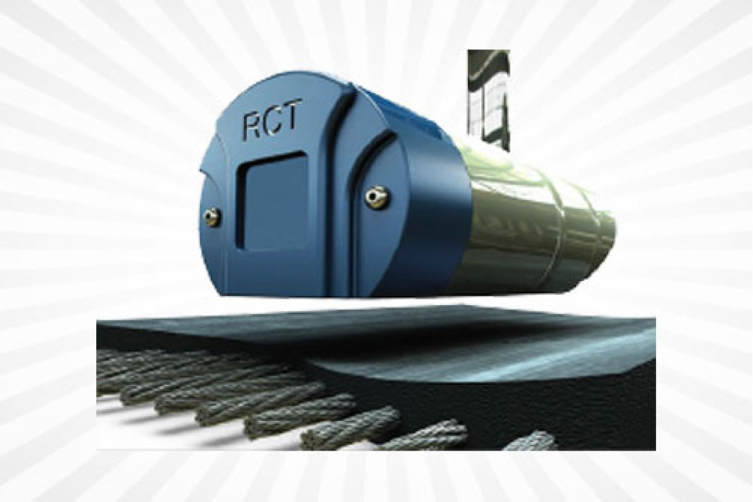
Rexline’s Remaining Cover Thickness (RCT) Monitor is an on-line device and can measure the remaining cover thickness of either the carry or pulley covers of Steel Cord belting, running under normal operating conditions.
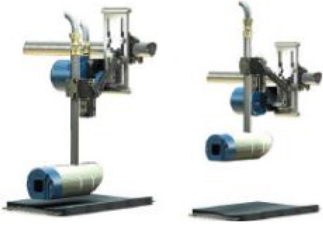
The device comes in two forms:
RCT Basic
This model is designed to be permanently fixed to a conveyor structure, with the underside of the Sensor Head 30.0 mm above the surface of the steel cords After installation and calibration, it produces a continuous 4 – 20mA signal output proportional to remaining cover thickness.. This signal is easily integrated into a site SCADA system. In new belting with say 15.0 mm carry cover, this places the Sensor Head15.0 mm above the surface of the belt.
RCT Alpha
The RCT Alpha has a “Safe Parking” feature, which allows the Sensor Head to be retracted to a parked position 160 mm from the belt surface, when not required to make measurements.
Cover wear rate in belting is relatively slow, even in short-cycle belts. This means that measurements need only be taken in weekly or monthly. Even then, usually two belt cycles provide sufficient data for trending purposes. This means that the RCT Alpha can be parked for most of its life cycle.
RCT Alpha is a very sophisticated device and is designed to communicate with the site over a Network connection and TCP. All data is logged on board in non-volatile memory, where it is available for download and analysis. A Tacho and belt Lateral Position Indicator (LPI) are included, which provide longitudinal and lateral belt position data, which is also logged.
The “Safe Parking” function can be either manual or automatic. In automatic mode, the device can be programmed to make its measurements at a nominated time and date, say the third day of every month at 10pm, for example. Firmware uses the LPI and a user-defined lateral ‘window’ to deal with the issue of belt wander.
After a defined interval, usually two belt revolutions, the device automatically parks and waits for data download instructions. The RCT Alpha comes with Proprietary software, which runs on the Network under Windows 98- WIN7. This allows device configuration and calibration as well as data download / viewing , including export of data to any destination as .CSV files.
There are two 4 – 20mA outputs, re-transmitting remaining cover thickness and belt lateral position. As with the RCT Basic, there is in-built Collision Reduction.
General
Both devices mount off a transverse steel tube, attached to the conveyor structure. This allows them to be positioned anywhere across the belt width. The sensing location is typically over the Tail Pulley.
The target area or ‘footprint’ being sensed is +/- 100 mm square. This means in a running belt, a ‘strip’ of belting +/- 100 mm wide is being measured. This being the case , it is essential to have the device located over the area of maximum wear across the belt. This location is determined from historical (or current) static belt cover profile measurements.
In the RCT Alpha, the LPI senses belt wander so that it is possible to limit data capture to the desired strip of belting.
Either device can be AC or DC powered.
The on-belt hardware is rated IP67 and IP68.
The electrical enclosure is 304 stainless steel, rated at IP69K (NEMA 4x).
All cabling is run in Anaconda Type EF Grey flexible steel conduit, rated at IP67, including fittings.